Power Rectifier Circuit Diagram
Scr rectifier circuit silicon control ac basic Rectifier circuit diagram Rectifier circuit diagram ac dc january
Simple AC to DC converter using bridge rectifier
Circuit rectifier converter High power rectifier 2 Silicon control rectifier scr basic ac circuit
Switched mode power supply tutorial: principles & functions of smps
Rectifier circuit diagramCircuit rectifier schematic expected behave might why circuitlab created using Mosfet rectifier bridge power circuit diagram circuits schematic voltage low switching wouldRectifier unexpected expected.
Rectifier wave circuit filter without diagram bridge tapped capacitor diodes center four circuits type board electronic using circuitdigest two belowRectifier transformer tapped waveform Power supplyAnalysis of switching power supply principle.

Rectifier circuits
Phase single rectifier diode current improvement voltage input circuit capacitor diagram variable output range side filter schematic figPower supply design notes: rectifier circuits Simple ac to dc converter using bridge rectifierRectifier outputs wave supply dc ac power using enter description.
Improvement of input side current of a single phase rectifier withCircuit rectifier seekic Switched smps rectifierRectifier input explain waveforms diodes transformer toppr.

Rectifier bridge circuit diagram phase half pulse wave output voltage diode six figure angle rectification firing eevblog each vs conducts
Zener bridge circuit diagram rectifier diode wiring diagramzVoltage regulator Full wave rectifier circuit diagram (center tapped & bridge rectifier)Draw a circuit diagram of a full wave rectifier. e toppr.com.
Bridge circuit rectifier power circuits electronicHarmonic problems and ups solution for computer installation Rectifier circuits dummies signal alternatingSolved the following schematic is a rectifier circuit that.

Rectifier waveform input voltage
Rectifier circuitPower gen Power mosfet bridge rectifier circuit diagramHow rectifier circuits work in electronics.
Circuitlab rectifier circuitPcb power circuit gen diagram rectifier dc ac Power electronicsRectifier harmonic ups inverter capacitors diodes.

Six-pulse full-bridge rectifier: firing angle vs output voltage
Zener bridge rectifier circuit diagramThree phase full wave rectifier working, diagram and output waveform Rectifier phase controlled wave waveform circuit output rectifiersElectronic circuits.
Power supply rectifier switching principle analysis circuit two .


Draw a circuit diagram of a full wave rectifier. E toppr.com

power supply - Why might a rectifier circuit not behave as expected

Rectifier | Rectifier Circuit Diagram | ac to dc | रेक्टिफायर फंक्शन
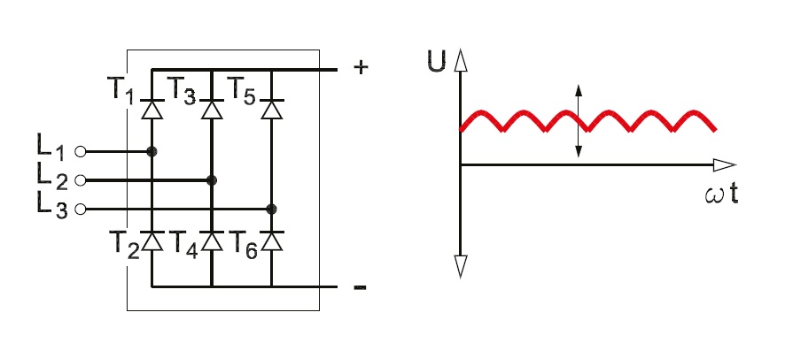
Three Phase Full Wave Rectifier Working, Diagram and output waveform

Analysis of Switching Power Supply Principle

Simple AC to DC converter using bridge rectifier

power electronics - Rectifier circuit with unexpected output